

Custom Medium Voltage Switchgear Design Guide for Reliable Power Systems
2026-08-25
Medium voltage switchgear rarely gets the attention it deserves—until a single point of failure brings an entire facility to a halt. Whether you're upgrading an aging substation or specifying new infrastructure, the difference between a resilient power system and a costly outage often starts with how the switchgear is designed. At Deepwill, we've seen too many projects compromised by off-the-shelf solutions that force square pegs into round holes. This guide breaks down the custom design approach we use to deliver medium voltage switchgear that matches real operating conditions, not just catalog specs. From arc flash mitigation to footprint constraints, you'll learn what actually matters when reliability is non-negotiable.
Tailoring Switchgear for Unusual Site Constraints
Not every switchgear installation happens inside a spacious, climate-controlled electrical room. Some projects force us to work within rock-cut tunnels, inside heritage buildings where walls can't be moved, or on offshore platforms where every square meter is fought over. These unusual site constraints often make standard switchgear dimensions, cable entry positions, and even cooling assumptions completely unworkable. That's when tailoring becomes essential.
A tailored approach starts with detailed site surveys and 3D laser scanning to capture the exact available envelope, including obstacles like beams, plumbing, and access hatches. We then adjust panel depths, split a lineup into smaller transportable sections, or re-orient busbars to fit around structural columns. For corrosive or high-humidity environments, we might upgrade enclosure gaskets and specify stainless steel hardware; for seismic zones, we add reinforced anchoring and flexible bus connections. Often the biggest win comes from rethinking cable entry — bringing feeders in from the top, bottom, or even the side can eliminate ugly, space-wasting conduit runs.
The goal is never just to "make it fit." A well-tailored switchgear installation keeps front and rear access clear for maintenance, preserves adequate arc-flash boundaries, and still allows future expansion without dismantling half the building. When done right, the switchgear looks like it was always meant to be there, even in a room shaped like a wedge or a tunnel with a curved ceiling. That level of integration reduces installation time, avoids costly civil works, and earns the respect of site engineers who have seen too many standard products forced into impossible spaces.
What Actually Drives Reliability in Medium Voltage Gear
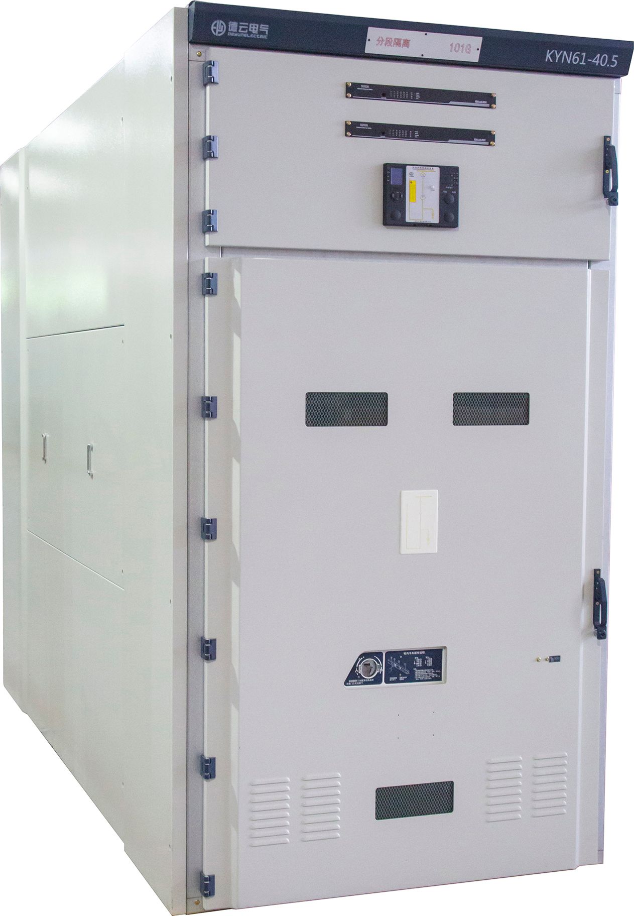
Reliability in medium voltage gear rarely hinges on the interrupting rating printed on the nameplate. Thermal expansion at busbar joints and cable terminations is a far more common culprit. Connections that pass a startup torque check can loosen after hundreds of load cycles, so the real difference comes from Belleville washers, correctly prepared contact surfaces, and infrared scans done while the gear is actually carrying current.
Insulation condition is another quiet driver. Dust, humidity, and condensation inside an enclosure slowly create leakage paths that invite partial discharge, especially around cable terminations and support insulators. Good enclosure sealing, properly sized space heaters, and keeping vents unblocked often extend service life more than adding another layer of monitoring electronics.
The mechanism behind the breaker faceplate deserves more attention than it usually gets. Dried grease, worn linkages, and weak closing springs cause nuisance trips and failed operations far more often than a rare short-circuit event. Equipment that lets a technician inspect contact wear and lubricate key points without a lengthy outage tends to stay in service longer.
Component Selection Without the Generic Defaults
Most component libraries ship with a predictable set of defaults: the same muted blue for every button, identical border radii across all cards, and a spacing scale that rarely survives contact with a real design brief. Choosing components this way feels safe, but it quietly erases the character of your product. The alternative is to treat component selection as a curatorial act—pick pieces that already carry a point of view, or be willing to tear out the generic styles before they harden into your interface.
A better starting point is to ask what the component refuses to do. A date picker that insists on a modal will fight a dashboard that needs inline editing. A table component built only for dense financial data will choke on image-heavy rows. When you stop hunting for the most popular option and start listing the constraints each piece imposes, the selection process becomes a negotiation rather than a checklist. That friction is useful—it forces you to define the visual and behavioral boundaries of your product before a single line of code is written.
There is also a quiet power in removing defaults you never asked for. Button hover states that glow, form fields that auto-capitalize, navigation links that underline on focus—these small assumptions accumulate into a generic feel. By stripping them back and rebuilding only what your users need, you end up with components that feel less like a template and more like a deliberate part of the system. The goal is not to be different for its own sake, but to make every default earn its place.
Thermal Behavior and Cooling Missteps
Most thermal failures aren't caused by a lack of cooling capacity, but by assuming temperature readings tell the whole story. Hotspots can persist while average junction temperatures look fine because heat spreads unevenly across a board or enclosure. A sensor placed near the edge of a heat sink might report 70°C while the die underneath sits closer to 110°C. That gap often gets ignored until performance throttles or components age prematurely.
One recurring misstep is treating airflow as an afterthought. Fans get added only after the chassis is packed, so cables and drive cages end up blocking intended paths. Recirculation zones form behind tall capacitors or dense fin stacks, pulling already-warmed air back over components that need cool inlet conditions. The result is a system that meets spec on paper but overheats within an hour under sustained load.
Thermal interface material choices also trip up even experienced teams. Applying more paste to bridge a poor mounting gap usually makes things worse; the layer thickness adds resistance, not conduction. Similarly, reusing a pre-cut pad after a heatsink has been pulled away introduces air voids that act like tiny insulators. What appears to be a minor assembly shortcut often shows up later as intermittent shutdowns or reduced boost clocks.
Protection Coordination That Survives Real Faults
Real faults rarely follow the neat assumptions baked into coordination studies. A phase-to-phase short can evolve into a ground fault mid-event, or a bolted fault can start as a high-impedance arc that refuses to clear quickly. When settings are tuned only for ideal conditions, the result is either nuisance tripping on harmless transients or delayed clearing that lets thermal and mechanical stress accumulate. The coordination that holds up in the field is built around the idea that the fault you planned for is only a starting point, not the whole story.
The most reliable schemes treat time-current curves as living documents rather than static deliverables. Engineers who revisit settings after every feeder change, motor addition, or transformer replacement tend to catch mismatches before they become misoperations. Adding a simple logic check, such as blocking instantaneous trips during inrush or using directional elements only where reverse fault current is actually possible, can prevent cascading outages that trace back to a single uncoordinated relay.
Field verification matters more than the software simulation. A breaker that passes a secondary injection test in the shop may still misbehave when its trip coil sees real fault current with harmonics and DC offset. Short-circuit testing at reduced voltage, or at least a thorough primary injection check through the entire trip path, exposes weak links that coordination software cannot model. Protection that survives real faults is less about finding the perfect curve and more about accepting that real-world behavior will punish any assumption you leave unexamined.
From Factory Tests to Field Confidence
A factory test bench gives you a clean, repeatable snapshot—but it rarely mimics the vibration, dust, or voltage spikes that equipment will meet in the field. A pass on the line is only the first data point, not the final word.
Building real confidence means cycling early units through pilot sites, logging every anomaly, and folding those findings back into the production line. Telemetry from the first hundred hours of runtime often exposes wear patterns that no accelerated lab protocol would predict.
That feedback loop—from test bay to field and back—turns a specification into a reputation. Operators stop asking whether the device will hold up and start treating its uptime as a given.
FAQ
Medium voltage switchgear generally covers systems operating between 1 kV and 38 kV, serving as the backbone for power distribution in industrial plants, hospitals, data centers, and utility substations.
Custom designs allow engineers to match exact footprint, busbar ratings, protection schemes, and environmental conditions, which is often the only way to fit tight electrical rooms or meet unusual duty cycles without compromising safety.
Busbar insulation quality, breaker interrupting capacity, arc flash containment, and thermal management under continuous load all play major roles, along with proper clearance and creepage distances for the site's altitude and humidity.
Start with the single-line diagram, fault current levels, load profile, and any applicable standards like IEC 62271 or ANSI/IEEE C37, then work with the manufacturer to finalize layout, control wiring, and future expansion space.
Routine tests typically include dielectric withstand, partial discharge, mechanical operation, and circuit resistance checks; for critical installations, a factory acceptance test with the owner's engineer present catches issues before shipment.
Enclosures can be reinforced with gaskets, heaters, anti-condensation systems, and corrosion-resistant finishes to handle salt spray, dust, or extreme temperatures while maintaining internal arc ratings.
Infrared thermography, torque checks on bolted connections, lubrication of moving parts, and periodic insulation resistance testing are more effective than time-based replacements, especially when combined with a digital monitoring system that tracks temperature and humidity.
Conclusion
Designing medium voltage switchgear for unusual site constraints forces a departure from catalog engineering. Instead of starting with a standard lineup and hoping it fits, the process begins by mapping physical clearances, cable entry paths, ambient conditions, and maintenance access. These constraints often dictate busbar orientation, enclosure depth, and whether withdrawable or fixed breaker configurations make sense. But fit alone does not deliver reliability. The real drivers are less about feature count and more about how insulation materials, creepage distances, and mechanical interlocks behave after years of thermal cycling and exposure. Component selection then shifts from generic defaults to specific choices: current transformers sized for actual burden, vacuum interrupters matched to expected switching duty, and protective relays configured with realistic settings rather than out-of-the-box values. This approach avoids the trap of building a switchgear that merely looks compliant on paper but struggles in service.
Thermal behavior is where many custom designs falter. Heat dissipation inside a compact enclosure does not follow simple nameplate math; busbar joints, ventilation openings, and the placement of auxiliary equipment can create hot spots that shorten insulation life. A useful design guide treats cooling as a verification exercise, using thermography or embedded sensors during factory heat runs rather than assuming forced air will compensate for poor layout. Protection coordination then has to survive real faults, not just idealized time-current curves. This means accounting for arc flash energy, ground fault behavior in high-impedance systems, and the actual clearing time of upstream devices. Finally, the transition from factory tests to field confidence depends on more than a certificate. It requires witness testing of critical functions, careful inspection after shipping, and clear commissioning procedures that verify interlocking, polarity, and relay logic on site. Only when those steps are integrated into the design philosophy does a custom switchgear assembly become a dependable part of the power system.
Contact Us
Contact Person: Julion
Email: [email protected]
Tel/WhatsApp: 8617351370631
Website: https://www.deyunelectric.com