

Top Ultrasonic Bubble Sensor for Reliable Liquid Detection
2026-09-17
An ultrasonic bubble sensor only earns its place in a fluid line when it stops surprising you. The problem is, many sensors work perfectly in a test bench but start drifting once the tubing warms up, the flow rate changes, or the liquid gets slightly cloudy. That gap between datasheet and real-world reliability is where most detection systems fall apart. Siansonic has taken a different route, designing ultrasonic sensors that stay consistent when conditions don't. If you're tired of chasing false alarms and missed bubbles, their approach to liquid detection might be the reset your system needs.
Listening for Bubbles: How Ultrasound Senses Gas in a Flowing Stream
Ultrasound offers a non-invasive way to detect gas bubbles moving inside a liquid stream. When a transducer sends high-frequency sound waves through the fluid, any bubble in the path reflects part of that energy back. The returning echo carries a specific signature, often a sharp spike or ringing pattern, which differs from the reflections produced by solid particles or the pipe wall. By tracking these echoes over time, engineers can estimate bubble size, velocity, and frequency without disturbing the flow.
In practice, the sensing system listens for changes in the acoustic impedance between the liquid and the gas. Because gas is far more compressible than water or oil, even a tiny bubble causes a noticeable jump in the reflected signal. Signal processing algorithms then isolate these transient events from background noise. This approach allows real-time monitoring of two-phase flows in pipelines, chemical reactors, and medical devices like dialysis machines, where unwanted air emboli pose a serious risk.
One advantage of ultrasonic bubble detection is its robustness in optically opaque fluids. Unlike camera-based methods, ultrasound does not require a transparent window or clean liquid. The technique can be tuned to focus on a specific region of the pipe, ignoring bubbles outside the measurement volume. As a result, it has found use in industries ranging from food processing to nuclear power, where reliable detection of gas pockets helps prevent cavitation damage, pump failure, or inaccurate flow readings.
When Tiny Air Pockets Cause Big Problems in Infusion Pumps
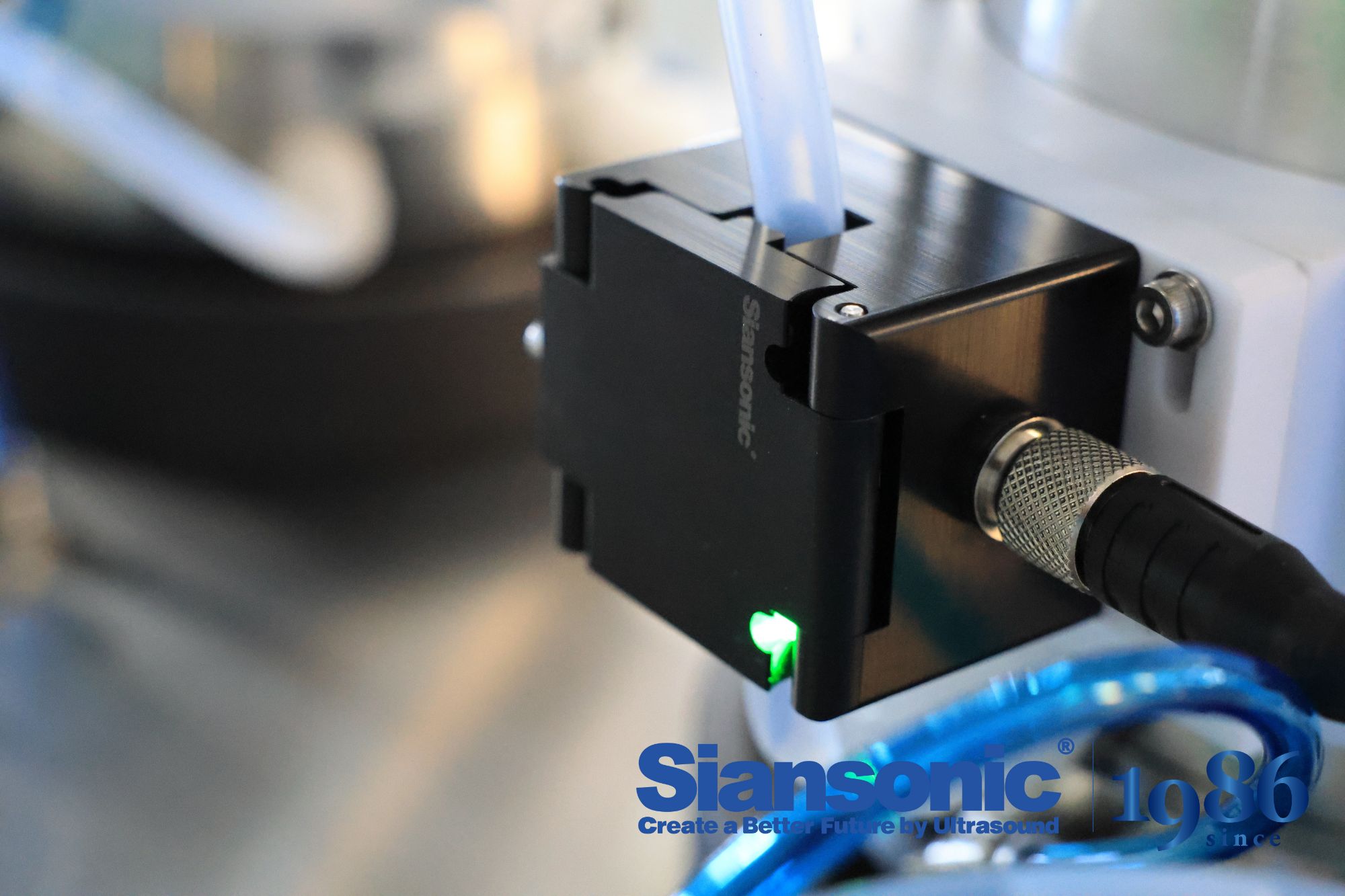
Infusion pumps are designed to deliver fluids with precision, but even a few microscopic bubbles can undermine that accuracy. When air pockets accumulate in the tubing or cassette, the pump's sensors may misinterpret the flow, leading to under-delivery or an unexpected bolus. In neonatal and pediatric care, where volumes are measured in milliliters, a stray bubble can mean the difference between a therapeutic dose and a dangerous gap.
Beyond dosing errors, trapped air can trigger nuisance alarms that desensitize clinicians over time. A pump that repeatedly stops for false air-in-line warnings forces nurses to interrupt therapy and manually clear the line, increasing workload and delaying critical medications. In some cases, larger air emboli may pass undetected if the sensor is calibrated for a different fluid viscosity, placing patients at risk of vascular occlusion.
Prevention hinges on meticulous priming techniques and regular inspection of the entire infusion set. Clinicians often tap the cassette gently to dislodge adherent bubbles before connecting the patient, yet this step is frequently rushed in busy units. Newer pumps incorporate advanced air-detection algorithms that differentiate between harmless microbubbles and clinically significant air volumes, but no technology replaces a careful, unhurried setup.
Materials That Keep Sensors Accurate in Harsh Chemical Streams
Sensor drift in aggressive chemical streams often begins at the wetted surface, not the electronics. A pH probe installed in a hot sulfuric acid line may lose its glass membrane within days, while a stainless steel conductivity cell in chlorinated brine develops pitting that shifts the cell constant. The right material pairing—usually a corrosion-resistant alloy or a dense ceramic—prevents the micro-scale surface changes that silently corrupt readings. Without this barrier, even a 0.2 mm etch can alter flow dynamics and create a stagnant layer where reaction byproducts accumulate, leading to false lows or erratic spikes.
Among metals, Hastelloy C-276 and titanium Grade 2 remain workhorses because they resist both reducing and oxidizing acids, yet they are not universal. For streams containing hydrofluoric acid or hot concentrated alkalis, tantalum or zirconium are often the only viable metallic options, though cost and machining difficulty limit their use. Ceramics offer a different path: yttria-stabilized zirconia and sapphire are nearly inert to most chemical attack and provide the added benefit of high abrasion resistance, which matters when the fluid carries catalyst fines or sand. A conductivity sensor with a sapphire sealed electrode, for instance, can survive years in a stream that would eat through 316L in weeks.
Polymer barriers have also moved beyond simple PTFE sleeves. Cross-linked PFA and ECTFE coatings, applied by electrostatic spray and then sintered, create a pinhole-free layer that handles aggressive solvents at temperatures up to 200°C. For optical sensors, a thin diamond-like carbon (DLC) window resists both chemical etching and particle impingement, keeping the light path clear. The real differentiator, however, is not just the base material but the seal geometry: a compression fitting that isolates the O-ring from the process fluid prevents crevice corrosion, which is often the hidden failure point. Field data from chemical plants show that sensors using these material combinations maintain calibration for 6–9 months, compared with 2–4 weeks for standard stainless steel bodies.
The Real Reason Some Bubble Sensors False-Alarm in Foamy Liquids
In medical infusion pumps and beverage filling lines, bubble sensors are tuned to flag any discontinuity in a liquid column. Foam changes the game. Instead of a single well-defined bubble, you get a dense cluster of gas pockets separated by thin liquid films. Many optical sensors interpret this frothy region as one large air gap because the repeated refraction events mimic the signal pattern of a void. The sensor never sees calm, clear liquid; it sees a chaotic scattering signature that crosses the alarm threshold.
Ultrasonic and capacitive designs have their own version of the problem. Foam attenuates ultrasonic pulses far more than a homogeneous liquid, and the echo timing becomes erratic as sound bounces between microbubble walls. Capacitive sensors, which rely on dielectric constant, read foam as a low-dielectric blob similar to an air embolism. Since these devices are usually calibrated with clean water or saline, even a modest head of foam can push the reading outside normal limits.
What makes this tricky is that the total gas volume in foam can be tiny, yet the sensor reacts as if a dangerous air slug is present. Engineers have responded by adding debounce timers, multi-wavelength optical checks, or signal pattern recognition that distinguishes dense foam from a true large bubble. But the root cause remains the same: foam creates an interface geometry that no simple threshold was ever designed to handle.
Mounting Distance, Tube Hardness, and the Forgotten Calibration Step
Mounting distance is rarely about just sliding a tube into place and tightening a clamp. The gap between the tube shoulder and the reference face determines how force travels through the entire assembly. Set it too short and you get preload that shows up as accelerated wear on the inner surface. Set it too long and the tube can shift under load, creating a chatter that no amount of damping will fully mask.
Tube hardness adds another layer that gets oversimplified on spec sheets. Average Rockwell or Brinell numbers don't capture the gradient you often find between the OD and the bore, especially after cold drawing or welding. A tube that reads within tolerance on the outside can still have a soft region right where the clamp bites, allowing localized deformation that quietly changes your mounting distance after a few thermal cycles.
Then there's the calibration step most people skip: re-zeroing the measurement tool at operating temperature, not just at room temperature. You can spend an hour dialing in the cold dimensions, bolt everything down, and then watch the first heat-up shift the tube by a few hundredths of a millimeter. That's not a measurement error—it's a different baseline. If you never calibrate under the same conditions the equipment actually runs in, you're chasing a number that never existed in service.
What Production Engineers Actually Change After Switching to Ultrasonic Detection
Once the ultrasonic detector replaces older touch-and-listen methods, the first thing that quietly disappears is the guesswork in scheduling. Engineers stop planning maintenance around fixed calendar intervals and start walking the floor with a handheld sensor that picks up leaks, bearing wear, or steam trap failures before they become visible. The routine shifts from "check everything every month" to "scan the high-risk assets weekly, and let the rest wait until the signal changes." That single adjustment cuts dozens of unnecessary inspections without adding risk.
The second shift happens in how teams talk about equipment health. Instead of writing vague notes like "sounds rough," engineers now log decibel readings and frequency bands for specific components. A pump that used to get a generic "needs attention" now has a baseline signature, and any drift from that signature triggers a targeted repair order. This forces a change in reporting habits: technicians stop using subjective language and start recording numbers that can be trended over months. Some plants even drop the old paper checklist entirely because the ultrasonic data feeds straight into a condition-monitoring dashboard.
Finally, the switch reshapes who gets trained and how. Since ultrasonic detection works on compressed air, gas, and electrical systems alike, a single technician can cover areas that used to require three specialists. Engineers spend less time coordinating experts and more time interpreting the same type of signal across different asset classes. In practice, this often means the maintenance crew shrinks or gets cross-trained on unfamiliar equipment, while the engineering team shifts its focus from firefighting breakdowns to optimizing energy losses that were previously invisible.
FAQ
Bubbles have a huge acoustic impedance mismatch with the liquid, so they reflect or scatter the ultrasonic signal much more strongly than most solid particles. The sensor's processing can also look at the shape and duration of the signal change to ignore passing debris.
Because it works through the tubing wall and doesn't care whether the fluid is clear, opaque, or blood. There's no contact with the liquid, so sterility is easier to maintain, and microbubbles are still caught even with wet or frosted tubing surfaces.
Usually yes, as long as the outer diameter and wall thickness fall within the sensor's specified range. The acoustic coupling may be slightly different between materials, but most modern units have enough dynamic range to compensate without manual adjustment.
The transmitting element sends a short ultrasonic pulse across the tubing. A gas bubble creates a strong echo or blocks a large portion of the pulse from reaching the receiver, causing a sudden drop in the received signal. When the signal falls below a set threshold for a few microseconds, the sensor flags a bubble event.
Detection itself happens within microseconds, but the practical response time is limited by how long the bubble stays in the acoustic path. At high flow rates, the sensor may only see the bubble for a millisecond or less, so a fast comparator and short pulse repetition interval are needed to avoid missing it.
Not if you're using a clamp-on style. You simply open the fixture, place it around the tubing at a straight section away from fittings or bends, and close the latch. It can be done while the line is running, though you should avoid pressing on the tube so hard that it deforms the inner diameter.
Very little besides wiping the transducer faces if any syrup or dust builds up. Occasional checks that the clamp hasn't loosened and that the tubing hasn't developed a permanent set are enough. Since there's no contact with the product, there's no internal cleaning or replacement of wetted parts.
Yes, bends and fittings can create turbulence or cause bubbles to travel along one side of the tube, making them harder to hit with the acoustic beam. For the most reliable detection, mount the sensor on a straight run with at least a few tube diameters of calm flow before and after the measurement point.
Conclusion
Ultrasonic bubble sensors work by listening for the acoustic signature that gas pockets create as they pass through a liquid stream. In infusion pumps, even tiny air bubbles can trigger dangerous air embolisms, so detecting them quickly and reliably is non-negotiable. But not all sensors hold up when the liquid is a harsh chemical or when the tubing material varies. That's why the top sensors use carefully selected materials for the transducer housing and acoustic coupling layer, ensuring consistent performance without degradation over months of exposure to aggressive solvents or sterilants. The physics is simple enough—sound waves scatter differently when they hit a gas-liquid interface—but turning that into a dependable signal in real-world conditions takes more than a textbook design.
False alarms are the silent killer of trust in any detection system, and foamy liquids are notorious for causing them. A bubble sensor that can't distinguish between a transient foam pocket and a true air slug will drive operators crazy and may lead to ignored alarms. The reliable ones rely on advanced signal processing that looks at the shape and duration of the acoustic reflection, not just its amplitude. Mounting distance from the sensor face, the hardness of the tubing, and a proper calibration step for each tube type are equally critical—skip the calibration and you might as well guess. Production engineers who switch to ultrasonic detection often report that they end up rethinking their entire fluid path: they standardize tube materials, add mounting fixtures to control spacing, and schedule routine verification checks. What they change is rarely the sensor itself, but everything around it that lets the sensor do its job consistently.
Contact Us
Contact Person: Ivy Zhang
Email: [email protected]
Tel/WhatsApp: +86 1081502288
Website: https://www.siansonic.com/